Full Bridge Converter Circuit Diagram
Full bridge converter circuit diagram Bjt h-bridge circuit details Simple mosfet inverter circuit diagram
Single Phase Full Bridge Inverter Explained - Electrical Concepts
Schematic diagram of induction motor Circuit diagram of full bridge converter [22] Rectifier capacitor resistor transcription electrical
Bridge converter
Discrete h-bridge circuit for enhanced vibration motor controlSimple ac to dc converter using bridge rectifier Full-bridge converter electrical schematic diagramFull-bridge inverter circuit.
Single phase full bridge inverter explainedConverter bridge circuit full diagram power high seekic Ir2110 circuits mosfet decouplingSingle phase half bridge inverter.

Phase-shift full-bridge converter control block diagram.
Bridge circuit bjt motor schematic driver pwm full mosfets details transistor arduino transistors opto hbridge diodes dc ground duty voltageBridge full converter diagram schematic electrical circuit seekic communication waveform typical Bridge bjt npn motor dc transistors pnp circuits circuit transistor collector 12v build use electronic switch driver nmos simple make120° mode inverter – circuit diagram, operation and formula.
Full bridge inverterProposed circuit for the full bridge converter Full bridge driversFull bridge.

Single phase half bridge inverter explained
Full bridge converter circuit diagramBridge full motor control circuit 4qd scheme gif tec controllers aka switching shows series used our Schematic diagram of half bridge converter circuitConvert photo to circuit diagram.
Inverter circuit diagram 120 mode operation phase three bridge power formula figure shown below electricalInverter phase circuit diagram principle Rectifier circuit diagramInverter circuit operation waveforms controlled.
![Circuit diagram of Full Bridge Converter [22] | Download Scientific Diagram](https://i2.wp.com/www.researchgate.net/profile/Yusufabubakar_Maiwada/publication/349669646/figure/fig1/AS:996166225383426@1614515944597/Circuit-diagram-of-Full-Bridge-Converter-22.ppm)
Full bridge converter circuit diagram
[solved] only problem 2! repeat problem 1 for the full-wave bridgeIr2110 mosfet driver circuit diagram Rectifier converter circuitSg3525 full bridge inverter circuit.
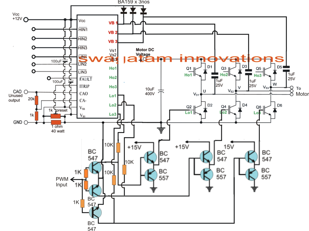
Sg3525 inverter circuit bridge full diagram using bootstrap mosfet circuits homemade channel capacitor mosfets high pdf schematic try post investigateHigh-power full-bridge converter circuit diagram [diagram] h bridge circuit diagramCircuit power bridge full converter supply seekic.

Circuit diagram inverter bridge full supply power phase single seekic
Converter circuitRectifier circuit waveform input Drivers infineon gateInverter explained electricalbaba.
Ir2110 circuitFull diagram bridge converter schematic electrical circuit seekic Bridge circuit converter full gr next above size click(a) ir2110 circuit, (b) full-bridge circuit the ir2110/ir2113 are high.

What is an h-bridge?
Educatore genuino elettronico inverter h bridge mosfet circuit perizomaFull-bridge converter electrical schematic diagram Full bridge converter circuit under repository-circuits -49490- : next.gr.
.

Schematic Diagram Of Induction Motor
![[DIAGRAM] H Bridge Circuit Diagram - MYDIAGRAM.ONLINE](https://i2.wp.com/theorycircuit.com/wp-content/uploads/2018/03/full-wave-bridge-rectifier-circuit-diagram.png)
[DIAGRAM] H Bridge Circuit Diagram - MYDIAGRAM.ONLINE

Rectifier Circuit Diagram | Half Wave, Full Wave, Bridge - ETechnoG

Single Phase Full Bridge Inverter Explained - Electrical Concepts

Convert Photo To Circuit Diagram
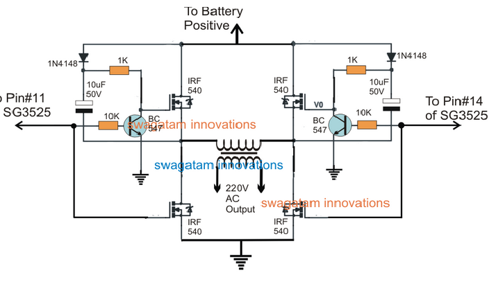
SG3525 Full Bridge Inverter Circuit